Introduction
Milling machines stand at the center of modern precision manufacturing, shaping everything from titanium turbine blades in commercial aircraft to aluminum transmission housings in electric vehicles. If you're involved in manufacturing, procurement, or engineering, understanding milling technology is essential to making informed decisions about production methods, equipment investment, and supplier partnerships.
Yet despite their ubiquity across aerospace, automotive, medical, and industrial sectors, many buyers and engineers lack a clear picture of how milling machines work, what types exist, and what to look for when sourcing machined components or evaluating equipment. That knowledge gap leads to costly mistakes: specifying the wrong machine type for a part geometry, overlooking critical capabilities during supplier qualification, or misunderstanding cost drivers in CNC machining quotes.
The evolution from manual hand-filing to fully automated 5-axis CNC machining centers has transformed milling from a skilled craft into a digitally controlled precision process. Today's CNC mills achieve tolerances as tight as ±0.0005" while machining components weighing up to 20,000 lbs — capabilities that make milling the go-to process for aerospace, medical, and industrial applications where precision and repeatability drive every decision.
TLDR:
- Milling machines remove material using rotating cutting tools against stationary workpieces to create precise shapes and surfaces
- Machine types range from manual mills ($5,000+) to 5-axis CNC centers ($500,000+), each suited to different production needs
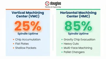
- HMCs achieve 85% spindle uptime vs. 25% for VMCs, driven by superior chip evacuation and automated pallet systems
- Standard CNC tolerances hold ±0.005", while precision aerospace work reaches ±0.0005"
- Selecting an ISO 9001:2015 and AS9100D certified shop gives buyers access to aerospace-grade tolerances without the capital investment of in-house equipment
What Is a Milling Machine?
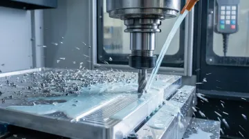
A milling machine is an industrial machine tool that uses rotating cutting tools to remove material from a stationary workpiece, producing precise flat surfaces, slots, contours, and complex 3D geometries. It's a cornerstone of subtractive manufacturing, where material is cut away layer by layer to achieve the desired shape.
The Working Principle:
The cutting tool (called a milling cutter or end mill) rotates at high speed , creating the cutting motion. The workpiece moves along three linear axes: X (left-right), Y (front-back), and Z (up-down). This coordinated movement between rotating tool and moving workpiece removes material in controlled layers, creating the final geometry.
Milling vs. Turning:
Understanding the fundamental difference between milling and lathe operations is critical for selecting the right process:
- Lathe: Workpiece rotates, tool remains stationary (ideal for cylindrical parts like shafts, pins, and bushings)
- Milling machine: Tool rotates, workpiece remains stationary (ideal for flat surfaces, slots, pockets, and complex 3D shapes)
Once you've confirmed milling is the right process, the operation follows a consistent five-step sequence.
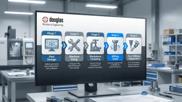
The Milling Workflow
- Part Design: Engineers create CAD models and generate toolpaths using CAM software (such as FeatureCAM or similar platforms)
- Machine Setup: Operators install appropriate cutting tools and configure machine parameters
- Workpiece Fixturing: Parts are secured using vises, clamps, or T-slot fixtures to prevent movement during cutting
- Milling Cycle: The machine executes programmed toolpaths at specified feed rates, depths of cut, and spindle speeds
- Post-Milling Inspection: Parts undergo dimensional verification using coordinate measuring machines (CMMs), granite surface plates, and precision gauges to confirm tolerances
Critical Technical Parameters:
Four parameters govern part quality and tool life:
- Rotational Speed (n): Spindle RPM, controlling how fast the cutting tool spins
- Cutting Speed (Vc): Surface speed at the cutting edge (measured in m/min or ft/min) that determines heat generation and tool wear
- Feed Rate (Vf): Workpiece movement speed relative to the tool (mm/min or in/min), affecting surface finish and cycle time
- Depth of Cut (ap): How far the tool penetrates the material, which influences material removal rate and cutting forces
These parameters must be matched to material hardness, tool geometry, and desired surface finish. Getting them wrong causes chatter, poor finishes, or premature tool breakage.
Key Components of a Milling Machine
Structural Foundation
The base and column provide the rigid structural support essential for precision. Any flexing or vibration in these components directly degrades dimensional accuracy. The knee and saddle enable vertical and cross-axis positioning of the worktable, while the worktable itself holds the workpiece using T-slot fixtures, vises, or clamps.
Spindle and Tool-Holding System
The spindle is the rotating shaft that mounts and drives the cutting tool. The headstock houses the spindle drive motor and transmission.
The arbor or tool holder connects the cutter to the spindle. Holder type affects both rigidity and tool-change speed:
- CAT: Common in US machining centers; reliable and widely supported
- BT: Similar to CAT but with dual-contact design for better high-speed stability
- HSK: Hollow taper shank offering superior rigidity at high RPM
Spindle orientation—vertical or horizontal—determines machine classification and capability.
CNC Control Systems
CNC (Computer Numerical Control) milling machines add a computerized control system that automates axis movement. Operators program these machines using G-code generated by CAM software, replacing manual handwheels and levers with precision servo motors. This automation delivers a level of repeatability manual operation can't match—critical for production runs and tight-tolerance aerospace work.
Types of Milling Machines
Vertical vs. Horizontal: Spindle Orientation
The most fundamental classification is spindle orientation, which determines chip evacuation, workpiece access, and ideal applications:
Vertical Milling Machines (VMCs):
- Spindle axis is vertical (perpendicular to table)
- Ideal for face milling, drilling, plunge cuts, and die sinking
- Better for flat plates, shallow pockets, and detailed surface work
- Average spindle uptime: 25% (chips accumulate on workpiece, requiring frequent stops for cleaning)
Horizontal Milling Machines (HMCs):
- Spindle is horizontal (parallel to table)
- Superior for heavy cuts, slot milling, and gang milling (multiple cutters on one arbor)
- Gravity pulls chips away from the workpiece, improving surface finish and cutting rework
- Average spindle uptime: 85%—vastly higher productivity for multi-sided production parts
- Universal tables and pallet changers allow multi-face machining in a single setup
Universal Milling Machines:
- Operate in both vertical and horizontal configurations
- Best suited for toolroom and low-volume work where setup flexibility matters more than production speed
Subcategories of Vertical Mills
Turret Mills:
- Fixed spindle, table moves perpendicular and parallel to spindle
- More versatile, favored for general-purpose work, prototyping, and job shops
- Lower rigidity limits heavy cutting
Bed Mills:
- Table moves only perpendicular to spindle; spindle moves vertically
- Fixed-table design provides significantly higher rigidity and load capacity
- Better for heavy-duty machining and large workpieces
Spindle orientation and machine subtype define the physical platform. Axis count determines how much geometric complexity a machine can handle in a single setup.
Axis Classification: Control Complexity
3-Axis Mills:
- Linear movement in X, Y, and Z only
- Most common configuration, lowest cost
- Sufficient for standard flat parts, pockets, and holes
4-Axis Mills:
- Add one rotary axis (typically A-axis rotation around X)
- Enables angular features and cylindrical work without repositioning
- Reduces setups for parts requiring multi-face access
5-Axis Mills:
- Three linear axes + two rotary axes (e.g., A and C)
- Enable complex 3D geometries in a single setup
- Critical for aerospace turbine blades, medical implants, and titanium blisks
- Reduces finishing time on complex components by up to 75% by maintaining optimal tool contact
- That capability comes at a cost — 5-axis machines typically run $200,000–$500,000+
Control Method Classification
Manual Mills:
- Operator-controlled handwheels
- Lowest cost, lowest precision
- Suitable for simple jobs, repairs, and training
- User-dependent accuracy; variations up to 0.127mm between parts
DRO-Equipped Manual Mills:
- Digital readout improves positioning accuracy
- Still requires manual operation
CNC Mills:
- Computer-controlled via G-code programs
- Highest precision, speed, and repeatability
- Standard for production and complex parts across aerospace, defense, and medical sectors
- Closed-loop feedback ensures identical geometry across 500+ units
For production environments where part-to-part consistency is non-negotiable — aerospace tolerances, medical implants, defense components — CNC is the practical baseline, not an upgrade.
What Can a Milling Machine Do? Operations and Applications
Common Milling Operations
| Operation | How It Works | Best For |
|---|---|---|
| Face Milling | Cutter edges on the end face and periphery; tool axis perpendicular to the surface | Smooth, flat top surfaces — the most common milling operation |
| End Milling | Cylindrical end mill with fluted sides; tool axis parallel to the surface | Profiling, slotting, cavities, and sidewall machining |
| Slot & Groove Milling | Side-and-face cutters for deep open slots; end mills for closed shallow slots | Channels, keyways, and T-slots |
| Thread Milling | Helical-interpolation toolpaths cut internal or external threads | Applications needing lower cutting forces; one tool handles multiple thread sizes |
| Gear Milling | Processes like Sandvik's InvoMilling run on standard 5-axis CNC machines using standard tools | External gears and splines without dedicated hobbing equipment |
Two broader categories govern how cutting action happens:
- Peripheral milling: Cutting occurs at the cutter's circumference — suited for deep slots, threads, and gear teeth
- Face milling: Cutting occurs at the end of the cutter — suited for flat surfaces and open cavities
Materials a Milling Machine Can Cut
Milling machines process a wide range of materials, but tool selection and cutting parameters must be matched to material properties:
Metals and Alloys:
- Steel, stainless steel, aluminum, titanium, copper, brass
- ISO S materials (titanium, heat-resistant superalloys) generate extreme heat and notch wear, requiring specialized tooling
Engineering Plastics:
- ABS, nylon, HDPE, PEEK (medical-grade)
- Heat-sensitive; require precise heat control to prevent deformation
Composites:
- Carbon fiber (CFRP), fiberglass (FRP)
- Extremely abrasive; standard carbide tools fail quickly
- Polycrystalline diamond (PCD) tipped tools are required for acceptable tool life
Specialized Materials:
- Ceramics, wood (in specialized applications)
Industry Applications
Aerospace and Defense:Engine components, structural frames, titanium blisks, and tight-tolerance parts requiring AS9100D certification. 5-axis simultaneous machining is critical for complex geometries like turbine blades and impellers. DM&E (Douglas Machine & Engineering), for example, holds both ISO 9001:2015 and AS9100D certifications and machines aerospace components up to 20,000 lbs with tolerances as tight as ±0.0005".
Automotive:Engine blocks, cylinder heads, transmission housings, and drivetrain components. Horizontal machining centers dominate high-volume production due to superior spindle uptime and multi-face machining capability.
Medical and Dental:Implants, surgical instruments, prosthetics. ISO 13485 certification is required, along with surface finishes of 0.1–0.4 µm Ra — tight enough to prevent bacterial biofilm and support osseointegration.
Industrial and Agricultural Equipment:Housings, brackets, shafts, connectors, and heavy structural components for construction, robotics, and agricultural machinery. These parts typically prioritize durability and dimensional consistency over extreme surface finish requirements.
Electronics:Heat sinks, PCBs, precision enclosures requiring tight tolerances and fine surface finishes.
Advantages and Limitations of Milling Machines
Key Advantages:
- Holds standard CNC tolerances of ±0.005" (0.13mm); precision aerospace work regularly achieves ±0.002" to ±0.0005"
- Handles complex 3D geometries, flat surfaces, pockets, slots, and threads across a wide range of materials
- Closed-loop CNC control ensures identical parts across production runs — critical for aerospace and medical applications
- Full automation reduces labor cost, eliminates human error, and enables lights-out manufacturing
These strengths come with real trade-offs worth understanding before committing to a milling approach.
Primary Limitations:
- Capital costs are significant — entry-level VMCs like the Haas VF-2 run $60,000–$80,000, while high-performance machines like the Mazak VCN-530C reach $120,000–$150,000; 5-axis centers often exceed $200,000
- HMCs with pallet changers demand substantial floor space, which affects facility planning
- CAD/CAM programming, G-code verification, and setup require skilled operators — this isn't plug-and-play equipment
- Tool changes and setup time add per-part cost for small batches, reducing efficiency at low volumes
When Milling Makes Sense:
Milling is the right call for complex 3D geometries, tight tolerances, hard materials, and multi-face parts where turning or grinding alone falls short. For straightforward cylindrical parts, a lathe is often faster and more cost-effective. The decision comes down to part geometry and volume — and for high-precision, multi-feature components common in aerospace and defense work, milling is rarely the wrong choice.
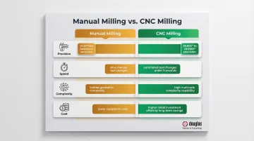
Manual vs. CNC Milling: What's the Difference?
| Attribute | Manual Milling | CNC Milling |
|---|---|---|
| Precision | User-dependent; low repeatability; variations up to 0.127mm | Consistently holds ±0.005" to ±0.0005"; closed-loop feedback |
| Speed | Slower; limited by human movement and manual tool changes | Rapid; automated tool changes (<3 seconds), rapid traverse up to 60m/min |
| Complexity | Limited to simple geometries | Executes complex multi-axis toolpaths impossible manually |
| Cost | Low equipment cost; high labor cost per unit | High initial investment; low per-part cost at volume |
Decision Framework:
Choose Manual Milling When:
- One-off repairs or simple prototypes
- Setup time under 10 minutes
- Simple geometries that don't justify CNC programming time
- Budget constraints prevent CNC investment
Choose CNC Milling When:
- Production runs requiring repeatability
- Tight tolerances (±0.005" or tighter)
- Complex geometries or multi-axis work
- Aerospace, defense, or medical applications requiring documented process control
Outsource to a CNC Machining Partner When:
Not every operation can justify the capital cost of CNC equipment, programming staff, and certifications. In those cases, a certified contract manufacturer like DM&E (ISO 9001:2015, AS9100D) can handle the work end-to-end. This approach works well when:
- Capital investment in CNC equipment or staffing isn't feasible
- Projects span multiple processes (machining, welding, finishing) and a single vendor reduces coordination overhead
- Aerospace, defense, or agricultural applications require documented quality management from design through delivery
- Reducing vendor count and purchase orders is a procurement priority
Frequently Asked Questions
What is a milling machine?
A milling machine is an industrial machine tool that removes material from a stationary workpiece using rotating cutting tools. It's used across manufacturing industries to produce precise flat surfaces, slots, contours, and complex geometries with tight tolerances.
What is the golden rule of milling?
The golden rule of milling is "thick to thin" chip formation: the cutter engages at maximum chip thickness and exits at zero. Climb milling (down milling) achieves this by feeding the tool in the direction of rotation, which reduces heat, friction, and tool wear.
How expensive is milling?
Manual milling machines start under $5,000, while entry-level CNC vertical machining centers range from $60,000–$80,000. High-performance CNC mills cost $120,000–$150,000, and industrial 5-axis machining centers can exceed $200,000–$500,000. Per-part milling service costs vary by material, complexity, tolerances, and volume.
Can I finance a milling machine purchase?
Yes. Most dealers offer loans, leases, and equipment financing programs—Mazak, for instance, provides $1 Purchase Option and Fair Market Value leases for 3–7 year terms. The U.S. Small Business Administration offers 7(a) loans (up to $5 million) and 504 loans (up to 25-year fixed terms) for heavy machinery purchases.
What is the difference between a milling machine and a lathe?
In a lathe, the workpiece rotates against a stationary cutting tool—best for cylindrical parts like shafts, pins, and bushings. In a milling machine, the cutting tool rotates against a stationary workpiece—best for flat surfaces, slots, pockets, and complex 3D geometries. Both are subtractive machining processes but serve different part geometries.
What materials can a milling machine cut?
Milling machines cut metals (steel, aluminum, titanium, brass), engineering plastics (ABS, nylon, PEEK), composites (carbon fiber, fiberglass), and certain ceramics and woods. Tool selection and cutting parameters must be matched to each material's hardness and machinability to prevent tool failure and achieve target surface finishes.